
“If you would be a real seeker after truth, it is necessary that at least once in your life you doubt, as far as possible, all things.” René Descartes
Addendum to the Fifth Edition of New Perspectives on Newtonian Collimation
Introduction
I’m hopeful that five will be my lucky number.
The fifth edition of New Perspectives on Newtonian Collimation is the product of more than five years of online discussions, more than five months of collaboration with Jim Fly and Jason Khadder getting the graphics just right, and more than five weeks of edits (resulting in five draft copies and various tweaks). You’ll probably notice it’s always more than five, and the fifth edition is more than a fifth edition–I even considered releasing it as the sixth! When I was nearly ready to publish the updated fourth, I had an epiphany that caused me to rethink the fourth edition’s collimation paradigm. So I cleaned the slate and started over, and ended up with something much more than an update.
The new graphics are my favorite part of the fifth edition (and you’ll see more of them in this addendum). The illustrations in the fourth edition were created from simple sketches I made at the eyepiece of a 20-inch f/5 ’scope I used in the late 1980s. The final line art was rendered at 72dpi on a 16-inch square palette and then reduced in size to 4X4 inches to generate a 300dpi graphic–the resolution of my first laser printer! In the fifth edition, high resolution 1000dpi illustrations coupled with an amazingly powerful 3D modeling application (POV-Ray) provide clarity and realism. To pick a more suitable “middle ground”, a 12-inch f/4.5 Newtonian was chosen for the 3D modeling application. The new text follows the same systematic approach I’ve used online to help many readers achieve precise Newtonian collimation and includes additional suggestions to improve optical (and mechanical) performance.
Vic Menard
October 2008
Click here for a sneak peek of the fifth edition.
The addendum is divided into sections, including:
The introduction
Notes on matching a sight tube to a telescope’s focal length
Notes on various secondary mirror alignment models
Additional image and animation files for the autocollimator
A brief review of previous addendum updates
Click here to review The New Model Illustrated
Notes on matching a sight tube to your ‘scope’s focal length
The first production sight tubes were long. I suppose the manufacturer’s were trying to get the best precision by keeping the crosshairs (located at the bottom of the sight tube) as far as possible from the pupil (located at the top). It didn’t take long for attentive users to realize they couldn’t see some of the important alignment elements because the field of view was too narrow for their shorter focal ratio ’scopes. Modern combo tool sight tubes are shorter to minimize this complication–most are about five times longer (measured top top bottom) than the width of the bottom aperture (f/5). Matching this ratio to your ’scope is important when setting the optimal offset secondary mirror placement, which is effected by aligning the bottom edge of the sight tube, the outer edge of the diagonal, and the reflected edge of the primary mirror (the reflection of the front opening of the tube assembly can also be included in this assessment, but if the front aperture is properly oversized, a small misalignment will be inconsequential). If you have a 2-inch focuser, CatsEye Collimation offers a variable focal length sight tube. You can simply set it to approximate your ’scope’s focal length (or even make it a bit shorter to provide a slightly wider field of view and discreet incremental steps between the aligned reflections) or you can set it to make each of the aligned circles appear to be precisely the same angular diameter.
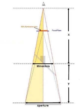
The graphic illustrates how the effective focal ratio and the optimal pupil distance for a variable length sight tube are determined. The simple mathematical solution follows:
Y = The Primary to Secondary Distance
X / Minor Axis = (X+ Primary to Secondary) / Aperture (similar triangles)
X = Primary to Secondary / ((Aperture / Minor Axis) – 1)
Subtract the intercept distance (the distance from the focal plane to the center of the secondary mirror), from the primary mirror focal length to find “Y”, the Primary to Secondary Distance. Once you’ve determined the value of X, you can find the Effective Focal Ratio for the sight tube by solving (Primary to Secondary Mirror + X) / Aperture. Similarly, the optimal sight tube pupil distance from the focal plane is equal to X minus the intercept distance. Depending on the size of the secondary mirror, you’ll probably have to rack the focuser out a considerable distance. If it’s possible, insert the sight tube flush to the shoulder of the focuser drawtube to minimize registration errors. Be careful not to insert the sight tube so far into the focuser drawtube that it hits the secondary mirror! If it’s impossible to use the optimized sight tube (even with the sight tube pulled away from the shoulder because of an oversized secondary mirror or limited focuser travel), try a shorter sight tube focal ratio and evaluate the concentric reflections through the available focuser travel.
Notes on various secondary mirror alignment models
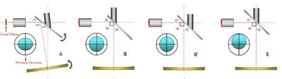
Note that the first four models have perpendicular focusers (all models provide correct axial alignment).
A – The New Model. Spider and secondary mirror are centered, and the primary mirror axis is tilted toward the focuser side of the OTA to provide the desired offset.
B – The Classic Offset Model. The spider is centered and the secondary mirror is mounted offset away from the focuser to provide the desired offset.
B’- The Classic Offset Model. Same as B except the spider is offset and the secondary mirror is mounted centered (relative to the spider) to provide the desired offset.
E – The Centered Model. The spider and secondary mirror are centered and there is no offset.
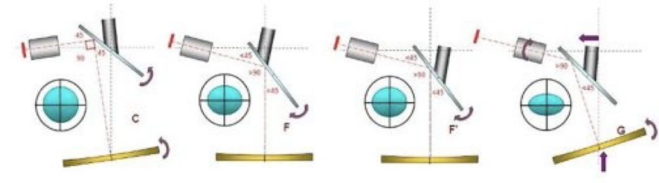
Note that the next four models all have tilted focusers.
C – A variation on The New Model. The focuser is tilted to provide a 90-degree intercept angle. The primary mirror axis is still tilted toward the focuser side of the OTA to provide the desired offset.
F, F’ and G – Variations with the secondary mirror closer to the primary mirror to provide additional out focus with an offset alignment.
Additional image and animation files for the autocollimator
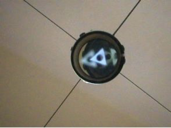
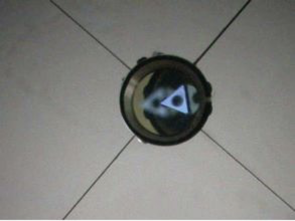
Images from an 11-inch f/5.4 Newtonian. (see Movie Clips) Both images have been carefully decollimated to keep the observed reflections in a similar orientation. Infinity II 2-inch autocollimator. The slight offset error of the autocollimator reflection in the diagonal reflection does not affect the axial collimation. It does slightly affect the percentage illumination at the edge of the field of view.
First Image–pure secondary mirror error–Note that the actual primary mirror center spot reflection (2nd from left) is centered, indicating the accurate alignment of the primary mirror axis. The focuser axis offset is indicated by the far left upright reflection (magnified two times via five reflections) and the far right inverted reflection (magnified four times via nine reflections). The second, dimmer inverted reflection can be seen between the actual primary mirror center spot reflection and the far right inverted reflection.
Second Image–pure primary error–Note that the actual primary mirror center spot reflection is no longer centered–it’s now slightly decollimated to the right. The primary axis offset is indicated by the far left reflection (magnified four times via five reflections) and the far right reflection (also magnified four times via nine reflections). The second, dimmer inverted reflection can be seen behind the actual primary mirror center spot reflection, indicating the accurate alignment of the focuser axis.
A brief review of previous addendum updates July 2004:
added section THE PRIMARY MIRROR CENTER SPOT AND “STAR COLLIMATION”
added information on “edge induced astigmatism”
added information on “the Barlowed laser”
performed some minor reformatting in preparation for the next addition
December 2004:
New images and movie links in the autocollimator section.
Removed “THE FOCUSER DIAGRAMS” section–replaced with actual images in the new…
PRACTICAL APPLICATIONS OF THE AUTOCOLLIMATOR section and
ANALYSIS OF THE AUTOCOLLIMATOR REFLECTIONS section.performed additional minor reformatting and corrections throughout the text.
April 2006
Revised focuser axial tolerances
Updated “the Barlowed laser”
October 2008
The majority of the data in the old addendum has now been incorporated into the fifth edition. The new addendum will be maintained as a resource for the fifth edition, and will continue to evolve as new material becomes available and as long as various collimation procedures will benefit from it.